![]()
Overview
ITW Southland manufactures gaskets for the automotive industry. As part of the quality control process these gaskets are heat cycled in temperature controlled chambers to simulate the real world heating and cooling that automotive engines encounter. The tests can be very long, sometimes several months in duration. ITW already had existing temperature chambers in place for the testing. The data collection that was provided by the chambers themselves however was inadequate and often unreliable. SDS was contacted to develop a new system for collecting the test data.
Equipment
The temperature chambers were located in a part of the building away from the technicians desks who would run the tests and were separated from each other by approximately 50 ft. The technicians wanted to be able to monitor the test from their desktop and there was not a convenient location on the shop floor to place a PC for running the tests. There was however access to the factory network near the temperature chambers. A networked based distributed I/O system was chosen for the hardware. This allowed each chamber to have the test hardware located conveniently next to the chamber and for the data to be collected on a remote PC located anywhere in the factory where network access was available. SDS chose National Instruments FieldPoint, a modular distributed I/O system, for the hardware. The hardware at each chamber consisted of the following:
This provided 8 channels of Thermocouple data and 8 channels of analog input at each chamber. This could easily be expanded out by the simple addition of extra input or output modules.
Software
SDS used LabVIEW to develop the system software. LabVIEW is a graphical programming language from National Instruments that helps speed the development of test, measurement and automation systems.
Setup
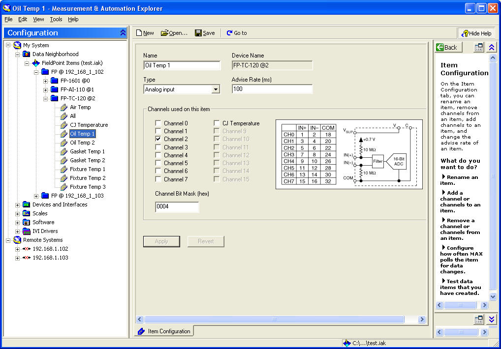
The setup for a test is a 2 part process. First the channels must be defined MAX (short for Measurement & Automation Explorer). MAX is a software configuration utility provided by National Instruments that allows you to setup and define all the channels in your FieldPoint system (as well as other hardware NI hardware). The screen below shows how you define the physical characteristics for one of the Thermocouple channels:

This screen below shows how you define and reference each channel in MAX. To access this channel you simply refer to 'Oil Temp 1' in the software.
Multiple configurations can be created, saved and retrieved.
After setting up the physical channels in MAX, the user selects the desired channels for a test from a list of channels defined in MAX as shown in the screen below:
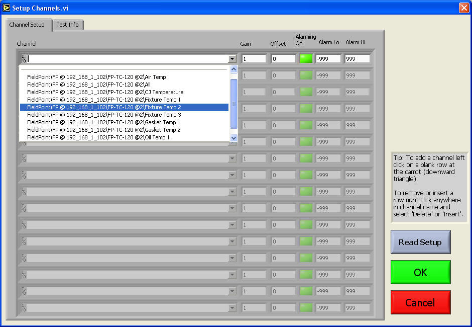
A gain, offset and alarming conditions can also be specified for each channel. Any combination of channels defined in MAX can be selected for a test. Test setups can be saved and retrieved for later use. The Test Info tab specifies other parameters and comments specific to a particular test.
Data Display
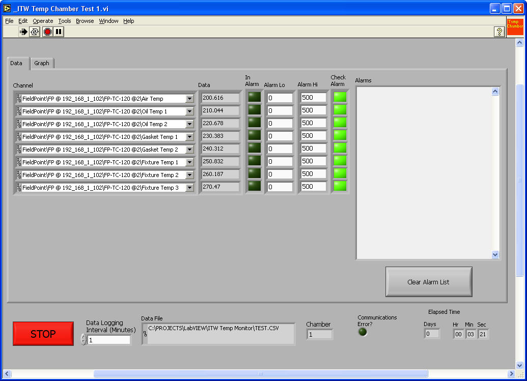
There are 2 screens that are available for viewing data during a test. These are displayed in a two tab format that allows easy switching between the two different views. The 'Data' view shows the current value for each channel. It allows the user to set alarm limits and turn on/off alarm checking for each channel. Any alarms are displayed in a list box on the right. The 'Data' view is shown below:
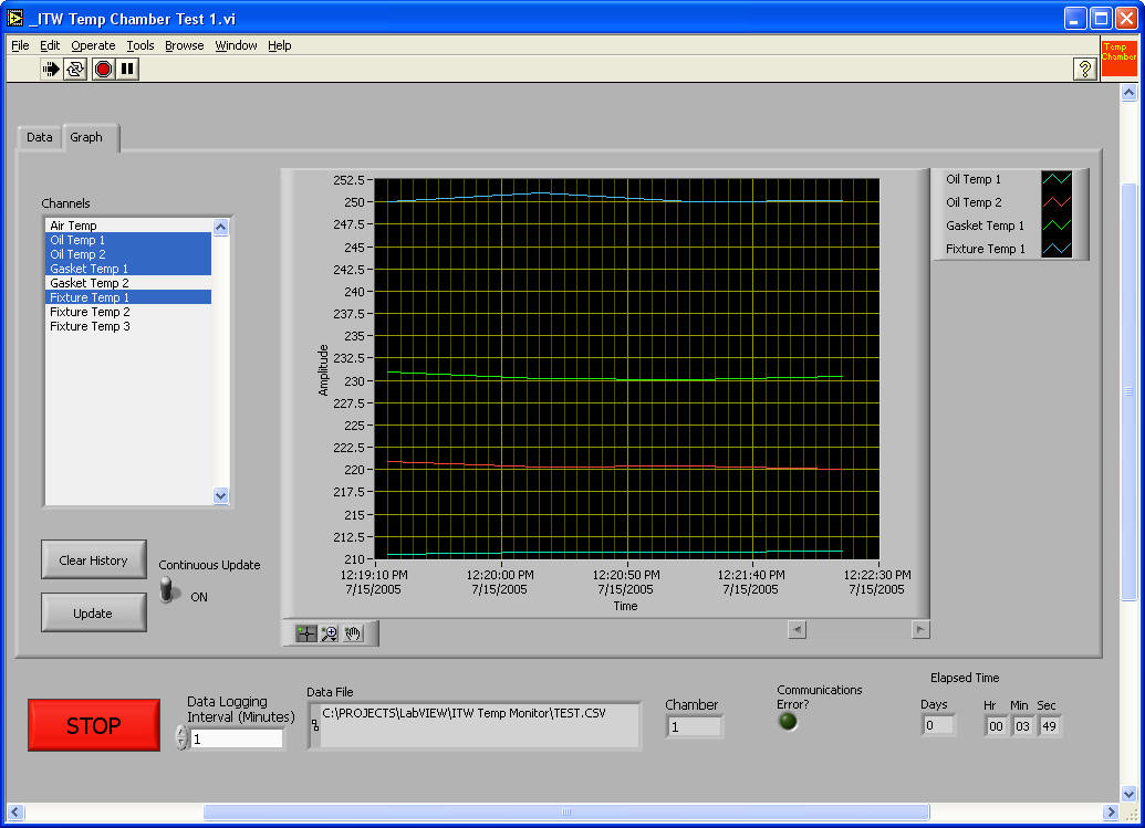
The other screen for viewing data is the 'Graph' view. This allows any set of channels in the test to be selected and displayed on a real time graph display. The user can clear the graph history, force an immediate update of the data or select continuous updating of the data. The graph can be zoomed in to an area of interest or scrolled backwards in time. The 'Graph' view is shown below.
Data Saving
Data is stored in Excel compatible file format. Data can be appended to previous test files.
Power Outage Recovery
Because the tests run unattended at nights, weekends and holidays the system needed to be able to recover from a power failure. Although a UPS can power a PC for short periods of time during a power interruption, their uptime is limited and the temperature chambers draw too much power for any type of backup power supply. The temperature chambers have the ability to start themselves back up after a power failure and it was decided that the test PC and software should have the same capabilities. If the test PC is forced to shut down during a power failure the software will restart automatically when the power returns. All previous test info will be retrieved from disk and the test will continue where it left off.
Channel Expansion
The system as presently configured for each chamber has 8 temperature channels and 8 analog input channels. The system has been developed in a manner that future channel expansion does not require any rewriting of the LabVIEW test software. To expand the system the user would simply add the desired FieldPoint hardware modules and configure them under MAX. Because the LabVIEW test software selects its channels from the list of channels defined in MAX the future expansion is only limited by the number of FieldPoint modules that can be connected. It would have been simpler to fix the number of channels for the system, but SDS strives to provide systems that are as flexible as possible to meet our customers needs.