![]()
Overview
The Test and Instrumentation Branch of the Advanced Aviation Technology Directorate (AATD) at Fort Eustis, Virginia tests helicopter engines for their infrared heat signatures. The hardware for this testing has been in place at the facility for many years. Several attempts by AATD personnel and by outside contractors had failed to meet their needs for an integrated test system. AATD contacted SDS to develop new system software. SDS had worked with AATD previously developing a fire control system for the BETRACS test range at AATD.
Equipment
A PSI 8400 Remote Pressure Monitoring System with six 16 channel scanners provides 96 channels of pressure data and atmospheric pressure. A NEFF System 470 with nine 16 channel scanner cards provides 105 channels of thermocouple temperature data and 32 channels of analog input. The analog channels are used to monitor engine parameters, vibration and any other data necessary to a particular test. The system PC communicates to the instrumentation via an IEEE-488 interface.
Software
SDS used LabVIEW to develop the system software. LabVIEW is a graphical programming language from National Instruments that helps speed the development of test, measurement and automation systems.
System Setup
Because of the large number of data channels in the system it was important to be able to easily reconfigure the individual channels for different tests. The channel setup allows the user to turn on or off any of the channels in the system for data collection. The user can specify a set of hi and lo warning and hi and lo alarm limits on a per channel basis. Each channel can be given a detailed description and a name. Channel setups can be saved and retrieved for later use.
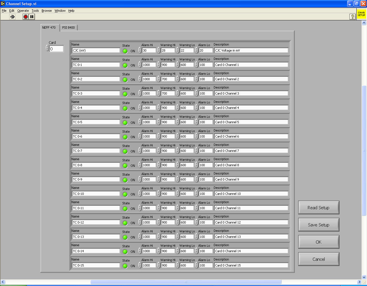
Channel Setup screen allows independent naming and alarming of each channel. Channels not in use can be turned off.
Data Display
One of the main design parameters of the new system was the ability to view all the data on screen at once and to graphically tell when data channels were at or approaching an alarm condition. Two table format displays were used to group the data from both the NEFF and PSI 8400 system. If the data is within the limits specified it appears with a white background. If a channel is over the warning or alarm limit, it is displayed with a yellow or red background accordingly. Similarly channels under the lower warning or alarm limits are displayed with cyan or blue. This allows the operator to easily spot channels outside the desired range.
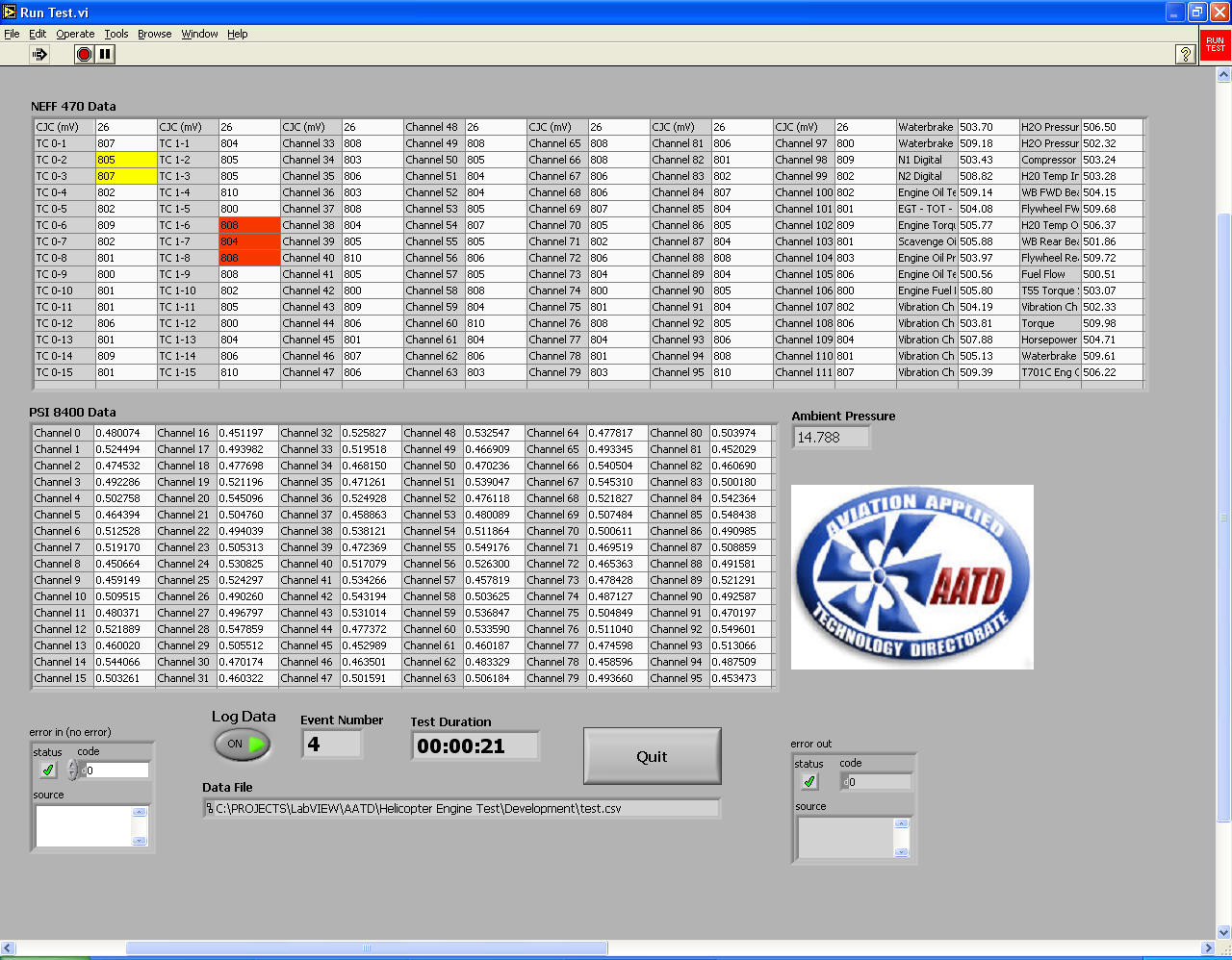
Main Test Screen displays 240 data channels and readings change color (note Yellow & Red cells) to indicate channels that are over/under their warning or alarm limits. All data simulated.
The system PC is equipped with a dual monitor display card allowing video output on two separate monitors. The second monitor is dedicated to the 32 engine and vibration channels with larger displays.
Display on secondary monitor shows engine parameters in larger displays.
All data simulated.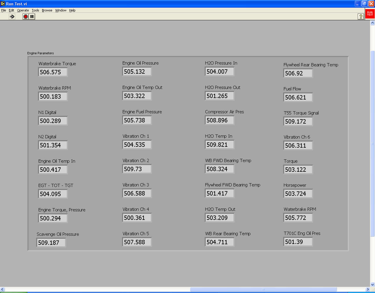
Calibration
Each of the 32 analog input channels can be calibrated by the user. A multi-point calibration using a least squares fit method is used to compute a gain and offset for each channel. A graph shows the actual data points collected versus the calculated points allowing the user to visually see how the computed values compare against the data points taken during the calibration.
Calibration screen allows user to select number of points to be used in
calibration and displays the results on a graph allowing user to accept or
decline the calculated values.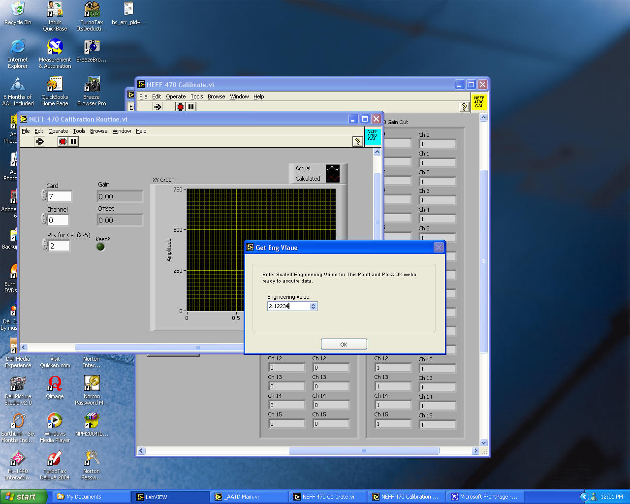
Data Saving
Test data is saved in a user specified Excel file. Data can be appended onto previous test runs if desired. Since data only needs to be collected at certain points in the test, a button on the screen allows the user to toggle writing to the data file on or off. If a test needs to be stopped and resumed later, the data can be appended onto the existing data file. In addition to the user specified data file, the system stores all data from the last 5 minutes in an archive file so the data for the last 5 minutes of the test is always available in case of an engine or system failure.